How to load film correctly into cutting plotters
Today’s blog post explains how to load film correctly into the plotter to achieve the best possible results.
In a previous article, we explained three key factors for achieving the best possible cutting results when using cutting plotters: contact pressure, blade depth and cutting speed. In today’s blog post, we’d like to expand on these factors by adding one important point and explain how to load film correctly into the plotter.
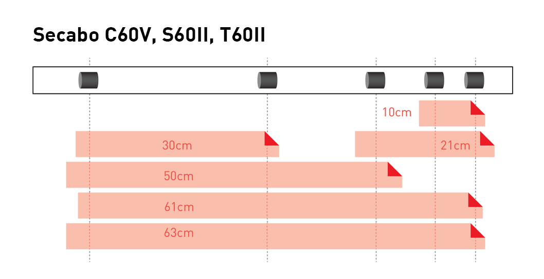
Generally speaking, there are various film width formats. Manufacturers and retailers typically supply rolls of film in standard widths of 21 cm, 30 cm, 50 cm, 63 cm, 100 cm, 126 cm and 152 cm. For all these typical film widths, most cutting plotters – such as the Secabo C 60V – provide a suitable combination of at least two so-called pinch rollers and grid rollers, which hold the film in place and feed it through the plotter. These pressure rollers cannot therefore be positioned anywhere along the cutting width, but only at the specified markings, where a grid roller is also located.
If you wish to load a film of a specific width into the plotter, it may not automatically work at the right-hand edge of the plotter, either because the film is too narrow and there is no matching counterpart at the left-hand end of the film, or because the pinch rollers are not evenly spaced across the film. In this case, you would need to select a different position for the pinch rollers to ensure optimal coverage by the grid rollers as far to the left and right of the film as possible. This is because the more symmetrical the arrangement of the pinch rollers on the film, the less warping there will be during film transport and, consequently, during cutting in the plotter.
To help you immediately identify where to position your specific film width in the plotter, we have provided three schematic diagrams below, illustrating the optimal arrangement of possible film widths in Secabo cutting plotters:
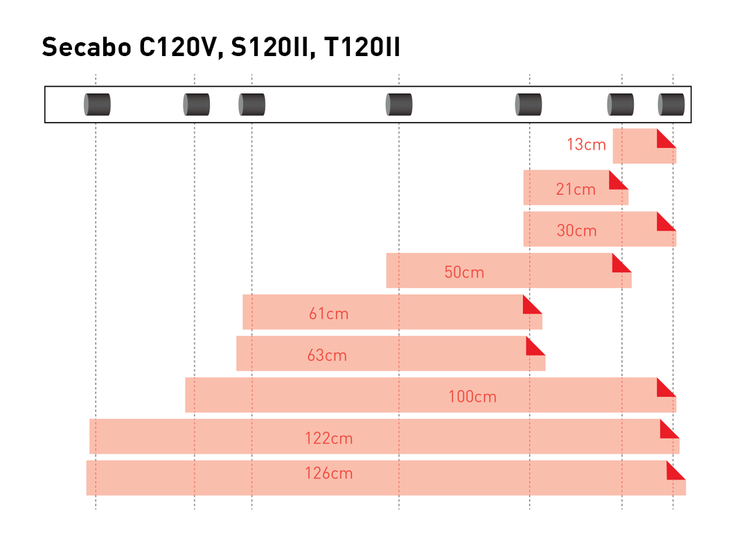
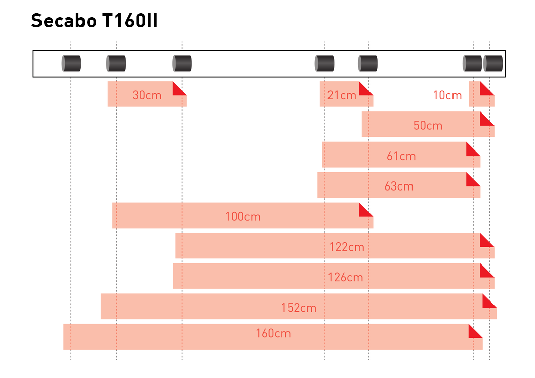
We’ve also created a video illustrating this and many other topics on our YOW! channel on YouTube. Enjoy watching, and don’t forget to subscribe!
> Watch the YOW! video ‘How to load film correctly into the cutting plotter’
> Click here to view the Secabo cutting plotters in the YOW! Shop